Introduction
There are two main types of UAS imagery: nadir and oblique. Nadir UAS imagery is taken perpendicular from an object. This is how most aerial images are taken. In UAS, these photos are most commonly used to create orthomosaics and DSMs. This is the kind of imagery which has been used for previous Geog390 UAS labs. In this lab, oblique imagery will be used. Oblique imagery consists of photos taken at an angle that is not perpendicular from an object. The most common angle is 45°. Oblique imagery allows for 3D modeling where the sides of objects can be measured because oblique pictures area taken all around the object. Common market uses of oblique imagery include emergency management, community planning, and property assessment situations (AIMS).Methods
For this lab, there are three sets of oblique imagery which will be used to create 3D models of objects. In previous labs, the 3D maps template was used, but because there is oblique imagery in this lab, no maps with orthomosaics or DSMs can be created. Thus, the 3D Model template will be used. The first study area is at the Litchfield frac sand mine located just southwest of Eau Claire along the Chippewa river. This imagery captured a bulldozer. Other lab data has been collected at this location. The other two sets of oblique imagery are from South middle school located in the southern part of Eau Claire. The second set of imagery captures a storage shed near the athletic fields, and the third set captures a pickup truck in the parking lot. All three oblique imagery sets were taken in a corkscrew like fashion starting from the ground and working up in altitude.Annotation will also be used in this lab. Annotation is a tool used in Pix4D after initial processing to remove unnecessary objects in each individual photo. There are three types of annotation: mask, carve, and global mask. Mask is used to rid of unwanted background objects and objects which occur in a few photos which overlap the main object which the 3D model is being created for. Carve, is used to remove the sky. Lastly, global mask is used to delete overlapping objects on the main object which occurs in almost all the photos. For this lab, only the mask tool will be used, even though the carve tool is specifically to remove the sky, the mask tool can do this as well. The data for this lab will also be processed without any annotation to draw comparisons between using annotation and not using annotation.
Image Set One: Bulldozer at the Litchfield Frac Sand Mine
The first step is to do the initial processing. After that, a copy of the Pix4D file was created so that the data could be processed with and without annotation. Then, images are ready for annotation. Below, figure 8.0 is one of the 5 images that were annotated using the mask template. To annotated the image, the pencil was clicked on in the upper right part of the figure. The template can then be changed in the lower right of the figure if necessary. The down arrow to the right of the mask template provides the options of mask, carve, and global mask.
 |
| Fig 8.0: Annotated Bulldozer Photo |
Image Set Two: Storage Shed at South Middle School
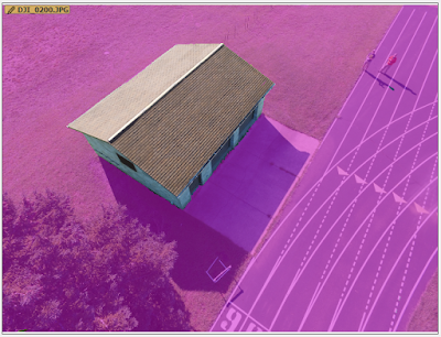
The same process used for the bulldozer is used for the storage shed. First. the initial processing was done, then a copy of the Pix4D file was created. After that, annotation was used to highlight the areas not wanted in the 3D model which can be seen below in figure 8.1. Lastly, a re-optimize was done using the annotation and the Point Cloud and Mesh processing was ran using annotation on the main file and on the copy file without using annotation.
 |
| Fig 8.1: Annotated Storage Shed Photo |
Image Set Three: Pickup Truck at South Middle School
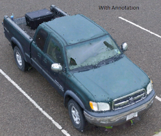
The same process used for the bulldozer and storage shed is used for the pickup truck. First. the initial processing was done, then a copy of the Pix4D file was created. After that, annotation was used to highlight the areas not wanted in the pickup truck's 3D model which can be seen below in figure 8.2. Lastly, a re-optimize was done on using the annotation and the Point Cloud and Mesh processing was ran using annotation on the main file and on the copy file without using annotation.
 |
| Figure 8.2: Annotated Pickup Truck |
Results / Discussion
A fly by video for all three 3D models using annotation were created. The bulldozer video can be seen in figure 8.3, the storage shed video can be seen in figure 8.4, and the pickup truck video can be seen in figure 8.5. These videos are a good visual of the 3D models.
Fig 8.3: Bulldozer Flyby Video
Figure 8.4: Storage Shed Flyby Video
Figure 8.5: Pickup Flyby Video
Bulldozer
To create comparisons between using annotation and not using annotation, .png files were created with roughly the same resolution. These were of the the final 3D model produced with and without annotation. The bulldozer image without annotation can be seen in figure 8.6, and the bulldozer image with annotation can be seen in figure 8.7.
To create comparisons between using annotation and not using annotation, .png files were created with roughly the same resolution. These were of the the final 3D model produced with and without annotation. The bulldozer image without annotation can be seen in figure 8.6, and the bulldozer image with annotation can be seen in figure 8.7.
 |
| Fig 8.6: Bulldozer Model Using Annotation |
 |
| Fig 8.7: Bulldozer Model Without Using Annotation |
Storage Shed
Next, a comparison was done between the 3D model of the storage shed with and without annotation. These can be seen below in figures 8.8 and 8.9 respectively.
 |
| Fig 8.8: 3D Model of Storage Shed Using Annotation |
 |
| Fig 8.9: 3D Model of Storage Shed Without Using Annotation |
Much like the bulldozer, there is really no difference between the models because there were no unwanted overlapping objects on the storage shed. There is a little difference on the top of the shed where poor quality is present. On the actual shed by South Middle School, there is not random plume on the top of the shed. The reason for this poor quality is unknown. However, both models experienced this issue. The other main issue is the random discolored pixels present in both models. The reason for this is also unknown, but could be because there weren't enough images taken of the shed.
Pickup Truck
Lastly, a comparison is done between the 3D models of the pickup truck with and without annotation. An image of the the model with annotation is displayed in figure 8.10, and an image of the model without annotation is displayed in figure 8.11.
 |
| Fig 8.10: Pickup Truck Model With Annotation |
 |
| Fig 8.10: Pickup Truck Model Without Annotation |
Conclusion
Although annotation wasn't necessarily needed for the oblique data sets used in this lab, many times it is. Oblique imagery can be used to create 3D models of objects as demonstrated in this lab. Based off the results from the pickup truck and the bulldozer, it seems that oblique imagery is most difficult to process when there is an object overhanging the desired model area. This happened in the bulldoze and pickup truck models where the tailgate was overhanging the ground and the scoop was overhanging itself. The flight path for taking oblique imagery should be decided based on the area surrounding the object. If there are no objects in the way of the desired object, then a corkscrew patterns starting from the ground and working up should be used just like the image pattern for the 3 oblique image sets for this lab. If there are many objects in the way, a different image aquisition pattern will have to be used.Sources
AIMS (Automated Information Mapping System), Oblique Imageryhttp://aims.jocogov.org/AIMSData/Oblique.aspx
Pix4D Help, How to Annotate Images in the Ray Cloud
https://support.pix4d.com/hc/en-us/articles/202560549-How-to-Annotate-Images-in-the-rayCloud#gsc.tab=0
No comments:
Post a Comment