Introduction
The goal of this lab is to become familiar with the C³P mission planning software and other mission planning essentials. These essentials will be covered, altitude settings will be discussed, and an overview of the C³P software will be given. A few main missions will be created, two in the Bramor Test Field area, and one in downtown Minneapolis. Issues with the C³P mission planning software will also be addressed. Then, an overall review of the C³P software will be given.Mission Planning Essentials
Prior to DepartingBefore departing, it is good to learn about the study site. Will there be hilly terrain, radio towers, cell towers, thick vegetation, crowds of people or other obstacles? These obstacles must be taken into account before starting the mission. Some of these obstacles may prevent the mission from taking place. For example, it is illegal to flight UAS platforms over large crowds of people. Before departing, it is also important to check to make sure that batteries are charged, that equipment is is working condition, and that all necessary equipment is accounted for. Lastly, one should check the weather before departing to make sure that mission day is a fair weather day. When checking the weather it is most important to look at precipitation and wind forecasts.
In the Field
Before deciding on a home, takeoff, rally, and landing point, the weather conditions must be checked. These include, wind speed, wind direction, temperature, and dew point. It is important to take off into the wind and to land with the wind. The vegetation, terrain, and man made features must also be assessed. The elevation of the launch site is important to know, because often UAS platforms will be flown at an absolute height above the launch site. Because GPS units are used for the flying of the UAS platforms frequently, it is important to make sure to stay away from objects which could emit electromagnetic waves. These could include power lines, power boxes, and underground cables. The units used should be standardized. Mixing between the English and Metric system increases the chance for error to occur. Lastly, one needs to make sure that the study area has a good GPS and cellular signal.
C³P Mission Planning Software
Creating a mission in C³P begins with moving the home, takeoff, rally, and land locations depending on the study area and the weather conditions. Then, a flight path is drawn using the Draw feature. This gives one the option to draw the path point by point, by area, or by line. The Draw by Area feature is the most commonly used. The missions settings then should be changed, which is discussed below. The mission can then be viewed in the 2D map which the C³P software provides or in in 3D through ArcGIS Earth or Google Earth.
For this lab, three main missions were created. The first mission took place in the Bramer Test Field. This is where the C³P software defaults the user to. the C³P allows one to control the mission settings which can be seen below in figure 9.0. It also allows the user to move the takeoff, home, rally, and landing locations. These are represented by T, H, R, and I orange circles respectively. The mission settings allow the user to alter the altitude, speed, overlap, sidelap, GSD, overshoot, camera type used, and the altitude mode of the mission. Generally, the altitude should be a comfortable distance above the highest object one is expected to encounter, the speed should be around 16 m/s to 18 m/s, the overlap should be at least 80%, the sidelap should be at least 70%, the GSD (pixel resolution) is usually left to the default, and the overshoot ( space for the UAS platform to correct itself when turning around) can be chosen based on the study area.
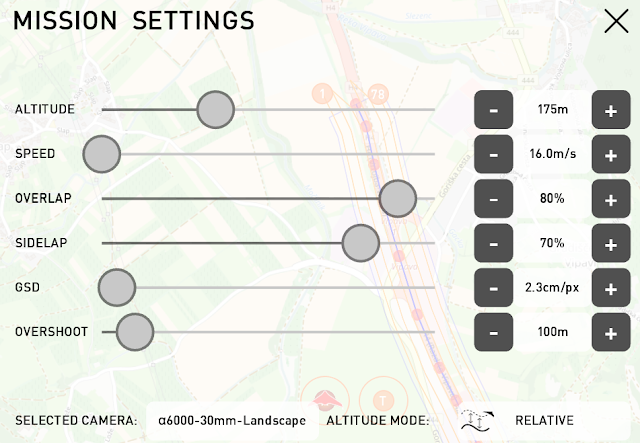 |
| Fig 9.0: Mission Settings |
Critical Altitude Settings: Height, Orientation, and Mode
To show the difference between altitude height, altitude mode, and flight orientation, 6 mini missions were created roughly covering the same areas. Relative altitude mode means that the UAS platform will always flight a certain height relative to the surface. Absolute altitude mode means that the UAS platform will always fly at the same altitude no matter how the terrain changes. Flight orientation refers to the direction the UAS platform is flown relative to obstructing terrain. All of the six mini missions use the draw area points feature. The T, H, R, and I circles are not shown in any of these missions because the point of these figures is to show the differences between certain settings. Besides terrain, altitude settings will need to be chosen based off of what anthropogenic features there are in the study area such as radio towers, cell towers, buildings, and other infrastructure.
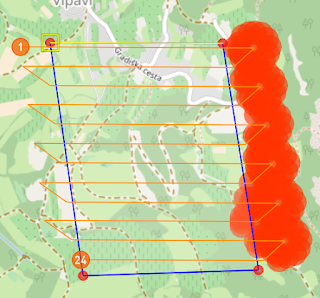
Figures 9.1 and 9.2 show the difference between using different absolute altitudes. Figure 9.1 has an flight altitude of 200 m, and figure 9.2 has a flight altitude of 175 m. All of the the other mission settings remained the same. Notice how figure 9.2 has red circles in the flight zone. This indicates that the UAS platform will crash if it is flown at that height. The red circles indicate that the UAS platform needs to flown at a higher altitude.
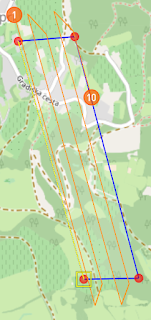 |
| Fig 9.1: 200 Meter Flight |
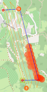 |
| Fig 9.2: 175 Meter Flight |
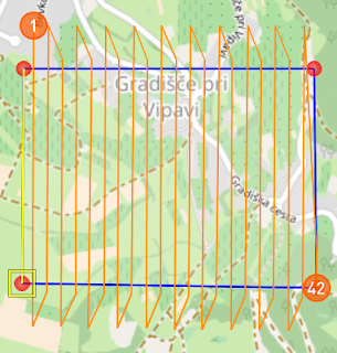
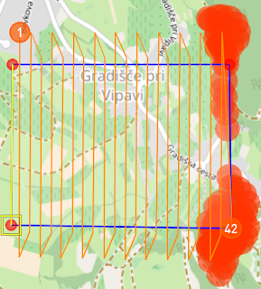
Orientation also affects flight planning. The difference between parallel and perpendicular orientation is shown below in figures 9.3 and 9.4. Figure 9.3 uses parallel orientation which goes with the hilly terrain and figure 9.4 uses perpendicular orientation which goes against the hilly terrain. Both areas roughly cover the same area, but the flight in figure 9.3 would be successful and the flight in figure 9.4 would not. Simply put, the UAS platform would hit something in the flight path in figure 9.4. This is because the UAS platform is instructed to turn around on the large hill. The flight in figure 9.3 would be successful because the flight path doesn't make the UAS platform turn around on the hill. It goes parallel with it instead.
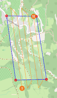 |
| Fig 9.3: Parallel Orientation |
 |
| Fig 9.4: Perpendicular Orientation |
Altitude mode also affects mission and flight planning. The difference between using relative and absolute altitude mode can be seen between figure 9.5 and 9.6, the altitude set in the mission settings for both is 140 m. Because the relative altitude mode changes the absolute altitude of the UAS platform in the flight in figure 9.5, it would be a successful flight. Figure 9.6's mission would not be successful because the absolute height of the UAS platform wouldn't change throughout the flight depending on the terrain. Therefore, when the UAS platform encounters a hill it would crash right into.
 |
| Fig 9.4: Relative Altitude Mode |
 |
| Fig 9.5: Absolute Altitude Mode |
Planning Missions
Figure 9.6 shows a mission created with the software. It uses the Draw Street Points feature to plan out the route along a road near the Bramer Test Field. The wind in this mission is coming from the east at about 3.6 m/s. The takeoff and landing zones are placed so that the UAS platform will takeoff into the wind and land with it. The takeoff and landing zones should be located in safe areas. They should not be located in the same area! If they are, the UAS operator and other spectators run the risk of getting injured because often the UAS is controlled from the home and launch site. One should also be careful to locate the landing area away from expensive objects such as cars. C³P, missions can also be displayed in 3D in ArcGIS Earth or Google Earch. The 3D mission for this one is shown in figure 9.7 using ArcGis Earth. The 3D view allows the user to see the surrounding terrain and vegetation near the mission site.
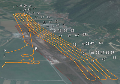 |
| Fig 9.7: 3D Road Sample Mission |
 |
| Fig 9.6: 2D Road Sample Mission |
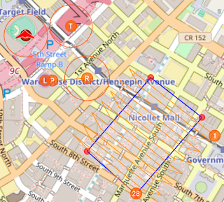
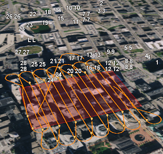
Another mission was created in downtown Minneapolis. This is shown below in 2D in figure 9.8 and in 3D in figure 9.9. The altitude for this flight is an absolute 140 m. This flight is completely illegal. The home and launch site is located in the outfield at Target Field, the mission flight area is all around very tall buildings in downtown, and the landing site is located on the roof of Target Center. The wind speed an direction is the same as in the previous sample mission.
 |
| Fig 9.8: Downtown Minneapolis Mission |
 |
| Fig 9.9: Downtown Minneapolis Mission |
An error with the C³P software has been discovered. In North America, the software will not tell the user if the flight will be successful or not. Many of the buildings in downtown Minneapolis are taller than 140 meters, yet there are no red circles in the 2D map indicating that objects will be hit. Also, the 3D map isn't 3D at all. The downtown buildings appear flat with the surface. This causes the software to think that the missions will be successful when it would be a complete failure. This kind of mission planning could potentially be misleading and dangerous.
Review of C³P Mission Planning Software
Overall, I found the C³P mission planning software to be very useful for planning missions. It even allows for simulation. I did a simulation which really helped me to understand all of the way points (home, takeoff, rally, land, and navigation) and how a mission works. In the beginning, I had to use the help quite a bit which was really useful. The help provides a whole tutorial to setting up a mission. The amount of information which the software is capable of providing is very nice. Being able to account for weather conditions, battery life, altitude and other information makes this very valuable software package. The measure tool is also handy because its a quick way to measure the distance between certain points.The downside to this mission planning software is that missions planned in North America cannot be totally depended on. This was shown in the mission located in downtown Minneapolis. This is a good reminder that technology isn't always to be trusted. People must do their own planning as well as using the mission planning software.
No comments:
Post a Comment